This is my build dairy (log) for my 95 Lamborghini Diablo kit car. It will be running on fumes (or gasoline vapors). I am explaining the build and how to run the car on fumes within this blog. There is also a video on dailymotion.com mark cooper sisqocracker that explains how this works.
Saturday, March 11, 2017
Mar 10 - Diablo door latch
I now have my passenger door latch installed. I made a lengthy video explaining the latch install and the plan for how to assemble the rest of the components inside the door.
Wednesday, March 8, 2017
Mar 8 - Marker lights are done
I've got some pics here of the finished product. I don't have any close ups but I did measure each one to make them parallel to the body lines instead of level with the ground. The two (lines) were fairly close together but off from one another. So I figured people would say it was crooked just because it didn't go along with the body line, so I went with the body line.
.
.
.
Got a funny here. I posted this up to my buddies. I told them that I have a washer and dryer to sell. hee hee :-D
Thanks,
Coop
Coop
Tuesday, March 7, 2017
Mar 7 - Them marker lights tho
I've come up with a pretty quick way to make the holes for the markers lights that are seen on the sides of the car. I used a hole saw that was the right size to match the clearance needed for my Hyundai marker lights. I drilled two holes that over lap. Then I trimmed the peaks down with a vibrating saw. I then finished off the clean up with a dremel tool that has a deburring tool attached to it.
On the rear I couldn't really put mine on the rear bumper as I should have done. It doesn't work out that way on this kit to fit those markers into that space (depth wise). Plus I wouldn't have a way to get in behind of them to work on them easily. but yeah, the depth doesn't work out any way so it's a moot point. What I did do was use a torpedo level to mark a level line right above the joint where the bumper meets the quarter panel. I measured across the width that I had and it came out to 9". So I centered the marker light on that space and kept its centerline to where the marker would be low and near the joint.
I marked the overall width I needed to fit the backing of the marker inside the hole. I centered that and marked both edges. Then when I lined up the drill with the hole saw on it, I could see if I was going to be far enough off of center to make the outside edge of the cutting circle come to the outer most edge of what I needed. I started the pilot drill bit into the body and let the hole saw cut about a 1/16th of an inch deep into the body then I backed it out and started the other hole that was beside of it and overlapping the one I already started. It really doesn't matter which one you finish first once you've got them both marked deep enough to keep the bit from wanting to wander.
On the front I measured down 2.5" from the top of the bumper and made some marks to cover the width of the marker. I then used my width of the marker (5") to make sure I left 1" to the edge near the front tire and measure back towards the front to mark the center for this marker. I also made marks like in the rear where I knew how wide my overall hole had to be to fit the back of the marker in it. It was 2.25" for this overall space. So I made a center of 1 1/8th" and marked the outside edges with the end of the tape and the 2.25" mark respectively. Then again I would eyeball the outside edge of the hole saw to that edge and kept on the center line to drill my hole and mark each before finally cutting all the way through.
I know that sounds like a lot to describe, but once you get it (what I mean) it goes very quickly. I bet I didn't spend 15~20 mins a pair front, or rear. I probably didn't have an hour in it and was done with all 4 holes. Trimmed out too. Ok, 2 hours out in the garage but not counting my screwing around and coming up with this method before I actually did any work. :-)
I'll post again tomorrow when I finish up by drilling the last 2 holes per marker where the screws mount the marker to the car. I've not done that tonight as I don't have much room to work on the car in the garage and I'm really cramped for space on the drivers side now. So I'll pull the car out and do it in the driveway and push it back in after I'm done. I'll get the nose mounted again as well. I need to start tightening the nose to the body so it'll retake its shape back. It's in pretty sad shape right now. Will take a little tightening up once a day I suspect until it fits like it used to again.
Thanks for your time.
Coop
On the rear I couldn't really put mine on the rear bumper as I should have done. It doesn't work out that way on this kit to fit those markers into that space (depth wise). Plus I wouldn't have a way to get in behind of them to work on them easily. but yeah, the depth doesn't work out any way so it's a moot point. What I did do was use a torpedo level to mark a level line right above the joint where the bumper meets the quarter panel. I measured across the width that I had and it came out to 9". So I centered the marker light on that space and kept its centerline to where the marker would be low and near the joint.
I marked the overall width I needed to fit the backing of the marker inside the hole. I centered that and marked both edges. Then when I lined up the drill with the hole saw on it, I could see if I was going to be far enough off of center to make the outside edge of the cutting circle come to the outer most edge of what I needed. I started the pilot drill bit into the body and let the hole saw cut about a 1/16th of an inch deep into the body then I backed it out and started the other hole that was beside of it and overlapping the one I already started. It really doesn't matter which one you finish first once you've got them both marked deep enough to keep the bit from wanting to wander.
On the front I measured down 2.5" from the top of the bumper and made some marks to cover the width of the marker. I then used my width of the marker (5") to make sure I left 1" to the edge near the front tire and measure back towards the front to mark the center for this marker. I also made marks like in the rear where I knew how wide my overall hole had to be to fit the back of the marker in it. It was 2.25" for this overall space. So I made a center of 1 1/8th" and marked the outside edges with the end of the tape and the 2.25" mark respectively. Then again I would eyeball the outside edge of the hole saw to that edge and kept on the center line to drill my hole and mark each before finally cutting all the way through.
![]() |
| Yeah, this one came out crooked. It still gets covered by the marker, so it's all good. :-) |
I know that sounds like a lot to describe, but once you get it (what I mean) it goes very quickly. I bet I didn't spend 15~20 mins a pair front, or rear. I probably didn't have an hour in it and was done with all 4 holes. Trimmed out too. Ok, 2 hours out in the garage but not counting my screwing around and coming up with this method before I actually did any work. :-)
I'll post again tomorrow when I finish up by drilling the last 2 holes per marker where the screws mount the marker to the car. I've not done that tonight as I don't have much room to work on the car in the garage and I'm really cramped for space on the drivers side now. So I'll pull the car out and do it in the driveway and push it back in after I'm done. I'll get the nose mounted again as well. I need to start tightening the nose to the body so it'll retake its shape back. It's in pretty sad shape right now. Will take a little tightening up once a day I suspect until it fits like it used to again.
Thanks for your time.
Coop
Sunday, March 5, 2017
Mar 5 - set that temp
I've now got a working temp control for the pre-heater element. It does switch on and heat up to well beyond where I want it to, and then it recognizes it has over shot and it turns off. Then once under temp again, it will switch back on. So I have some progress there.
It was only at the end of the day when I got this far and had already switched off my computer so I'll have to start over tomorrow with the RasPi and reset it to a default install. Then I can reload the Arduino and Teensy stuff on it and then go again with trying to adjust my program. I was updating the program on my laptop and then trying to test, which wasn't working out. I didn't find this out 100% until I had plugged the teensy back into the RasPi and everything worked as it should had.
I also adjusted the dip switches on the back of my tach so it'll be good to see if that has corrected my tach output now. Would be nice to see a normal idle showing on the tach, instead of it claiming to be 250 rpm. :-)
So maybe tomorrow I can set the temp much higher than where I have it now and add a couple of features, where it will be easier to tell what the temp is and maybe even an easy way to set the temp instead of using a computer to set it. May be getting ahead of myself there.
I'm just glad to be over the hump to where I know have an automated means for controlling the power to the heating element and it will regulate the temp within some margin. Now I can focus on figuring out what that temp should be and automating more of the processes that it takes to make this as easy to use as a normal fuel injected car is.
Thanks,
Coop
It was only at the end of the day when I got this far and had already switched off my computer so I'll have to start over tomorrow with the RasPi and reset it to a default install. Then I can reload the Arduino and Teensy stuff on it and then go again with trying to adjust my program. I was updating the program on my laptop and then trying to test, which wasn't working out. I didn't find this out 100% until I had plugged the teensy back into the RasPi and everything worked as it should had.
I also adjusted the dip switches on the back of my tach so it'll be good to see if that has corrected my tach output now. Would be nice to see a normal idle showing on the tach, instead of it claiming to be 250 rpm. :-)
So maybe tomorrow I can set the temp much higher than where I have it now and add a couple of features, where it will be easier to tell what the temp is and maybe even an easy way to set the temp instead of using a computer to set it. May be getting ahead of myself there.
I'm just glad to be over the hump to where I know have an automated means for controlling the power to the heating element and it will regulate the temp within some margin. Now I can focus on figuring out what that temp should be and automating more of the processes that it takes to make this as easy to use as a normal fuel injected car is.
Thanks,
Coop
Wednesday, March 1, 2017
Mar 1 - one program away
I've got the last of the physical install stuff done for the next iteration of the fumes testing. I've got the solid state relay installed. It is controlling the power line to the heating element being allowed to connect or not. It has a 5v turn on that is micro-controller switched based on the temperature it sees in the box and being mounted up against the element itself. This will avoid the element reaching a temp high enough to have any more small explosions in the box.
Here's the solid state relay.
Control is on the bottom, the power line I spliced into is on the top. I'm repurposing the same setup that was going to watch the larger vaporizer box with and control the vacuum to the EGR, is now being used here instead. I think being 100% electrical I can be more accurate in the temp control. We'll see.
It takes a little longer to warm up, but allows me to save more fuel on cold starts than it would have in the other method. I plan to put some sort of gauge to see the temp at all times. I'm thinking because it is already run by the teensy, that I could run a servo that has a hand on it and make my own gauge to watch. Easier to know the actual temp for cold starts. That would be nice to know over having just an LED. That was my original idea, I was going to light an LED with an icon in front of it that looks like the glow plug warming coil icon that Diesels use when they cold start. I'd rather have the gauge and know the actual temps.
Thanks for your time. Hopefully this will inspire others to do similar stuff.
Take care,
Coop
Sunday, February 26, 2017
Feb 26 - finish up that breath
I closed up the intake tube today. I got the slot cut out to allow the heating element to exit from inside the elbow. I got the clamps on it. Repositioned the air filter so it can get fresh air from outside.
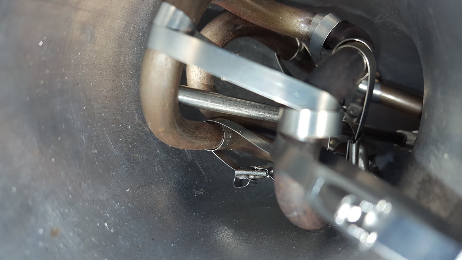
I thought I would show what the element looks like up inside the elbow once it is ready to go before I add the other bits where it blocks the view of the one tie wrap I use to hole the element in place. I've got a hole drilled into one end of the elbow so I can run a tie wrap through that to pull the element to the one end. That makes the back end set its location so it can't be moving around in there once set with the cap on the top.
Then I added a piece of foam rubber with electrical tape wrapped around it (to stop the flaky bits from getting sucked into the motor itself). I have a stainless steel tie wrap on that as well. there are multiple pictures so I can try to get enough angles to make sense of what you can see. When you see the 2.25" pipe doing a 180 up near the camera view, you're looking down through the quarter window behind the passenger's door, to see that view.
I thought I would show what the element looks like up inside the elbow once it is ready to go before I add the other bits where it blocks the view of the one tie wrap I use to hole the element in place. I've got a hole drilled into one end of the elbow so I can run a tie wrap through that to pull the element to the one end. That makes the back end set its location so it can't be moving around in there once set with the cap on the top.
Then I added a piece of foam rubber with electrical tape wrapped around it (to stop the flaky bits from getting sucked into the motor itself). I have a stainless steel tie wrap on that as well. there are multiple pictures so I can try to get enough angles to make sense of what you can see. When you see the 2.25" pipe doing a 180 up near the camera view, you're looking down through the quarter window behind the passenger's door, to see that view.
![]() |
| Can also see the temp probe touching on the back of this 180 bend at the bottom. Which appears on the left in this image. |
![]() |
| Can see the opening in between the heat elements leads. |
Friday, February 24, 2017
Feb 24 - proper breathing
So today I spent most of it trying to fab up a first run of what I want to do for my naturally aspirated hot fumes car. I needed to make an adapter to go from a 3" intake to a 2 1/4" pipe but offset it in such a way as to make room for the heating element to exit the 3" elbow it sits inside of.
I've got some pics here that show the process as I was trying to keep up with the various steps as I went along. People can comment on here if they would like more details about this piece. If this isn't all going together for you, I'm sure it will once you see what comes next.
![]() |
| Adapter is mounted on the bottom of the 3" elbow. |
![]() |
| I will cut holes and slit the vertical on the adapter to allow the heating element and K-Type thermocouple to exit this piece. |
![]() |
| Looking down from the top. |
![]() |
| Looking Back from the Front. |
![]() |
| Looking from right in front of the rear tire. |
Subscribe to:
Posts (Atom)