Thursday, April 28, 2016

Apr 28 - Exhaust temp probes are installed

As I finished this up today as well, I'm putting it down as today's progress.  I worked in between other regular jobs for work and amazingly got a lot finished up today.  Battery box, temp probe for the vaporizer box and this one to finish up the temp probes for the exhaust manifolds.

So I had one post already where I had to weld that one up as it didn't go so well for the drilling and threading of that EGT bung into the manifold.

But I got this finished up today by taking an O2 plug and drilling it out and tapping it for the other EGT probe to fit in it.  That went pretty well and it was able to be screwed together.  We'll see if it leaks or not and needs to be welded after all, but in both of these weld cases, it is one where only the bung is being welded, I will always be able to replace the probe in either of them.

Some pics of that work being done and completed.


Apr 28 - Vaporizer box - more details

In case you're following me as I go along... The box I have is a Type 4 from frozenboost.com

There are a couple of modifications that need to be made to the box to make it become a vaporizer instead of an intercooler.  I left off an update when it happened as I hadn't figured out how I was going to tackle the temp probe that goes into the same box.  I wound up putting it on the opposite side of where I was originally thinking that I would put it.  I am trying to have it right in front of the fuel injector so I know the temp at the hottest spot in the box and right near where the fumes try spraying into the fins of the intercooler section.  The pictures will help make this more sense.

I bought a fuel injection bung kit for a 4 cylinder fuel rail from eBay.  The title of the item I bought was called "Raw Dash 8 Fuel Rail & Injector Bung Set - 17" RAIL AND 4 BUNGS".  It was from this seller.  The fuel rail itself is ready to go for a 1/2" NPT tap to be turned in it.  Makes it easy to adapt some fuel lines to it.  The fuel injector bungs have a shoulder cut into one end on them.  You can use this to set the bottom of the injector appropriately and then cut the length down as it is made for you to decide how long that bit should be.

The intercooler I was talking about is here.  It has a 3" intake and outlet on it.  Has M8 x 1 bolt holes in it for mounting.  I had a machine shop cut the hole for the fuel injector bung to drop into.  We set the depth to being flush in the back and protruding into the air intake nearest where the air enters the unit.  We made the hole about .030" slotted long front to back so we could angle the bung so it wasn't spraying straight down.  You can see some of these details in the pictures also.  The K type thermocouple that I bought for a temp probe in this unit came from China and was listed on eBay here.  They list it as a 3/8" NPT fitting, but it is actually M8 x 1.25.  I drilled and tapped a spot for that as you can also see in the pics.  I just forced the probe down in between 2 of the passages for the heating (in my case, cooling by design) to run through.  It reaches about 3/4" down into there.  I should get good readings of the temp as it enters this section.  I want to ensure that I don't ever allow this temp to get too high.

If there are questions, leave them in the comments section and I can provide more detail about these things.

The off-center angle I'm using here is to ensure the probe goes down in between two runners inside.  If you line this up perfect top-down, it will run right into one of the runners and as I would be tapping this for the probe to be installed into.... You get the idea.


Apr 28 - BATT-ah-RY!!!

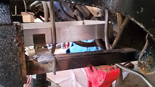
I was struggling to get this one done as I needed time to do it and everything else kept coming up that needed done.  So I worked in between other jobs on this one getting done and still managed to knock it out today.  There are some little stragglers that need tidying up but it is in there!  I took pictures of what it looks like in the build up of what I've done.

Any comments will be well received (minus trolls of course).

I got done last night; Aluminum tray for the battery box to sit in and the brace that is welded to the square tube that it is sitting on.  Then today I got the tabs added onto the brace so there is no left/right movement.  And also added the mount on the firewall to support the front bit and stop any fore/aft movement.


Monday, April 25, 2016

Apr 25 - when your drill and tap

When your drill and tap turns into eff it and weld it.

I did drill and tap it. But there were burrs at the bottom of the drill hole. Once I got my tap through those so it was clean, the tapping was too deep for npt.  So I only had about two full threads tightened down by hand tight.  So I said screw it and tightened it down and welded it up so it can't leak.

Apr 24 - Custom Exhaust?


I pulled the manifolds back off so I can put my EGT sensors in them.  I've discovered that it will be much easier to mount them into the locations where the stock O2 sensors were.  One side will need drilled and tapped and the other will use the existing O2 threaded location with a bushing in it.

I'm sourcing that bushing now, or may just use a plug and will drill and tap that myself.  Whichever comes first in my search.  I've checked with English NPT sizes and the threaded O2 hole is smaller than 1/2" but larger than 1/4" NPT.  I don't think it is 3/8" NPT, but am suspecting that it is metric.

Anyone want to leave a remark on this, I'd appreciate it.  These are stock exhaust manifolds from a 93-97 f-body, LT-1 motor.  Specifically from a 95 if it matters.

Monday, April 4, 2016

Apr 4 - Getting hosed... at least ran some

I've got some of my radiator hose routing in the car now.  I looked around and couldn't find any 1.25" Tees for use on the radiator hose and cooling system.  So I did see where a guy had made up his own with regular plumbing parts.  Looked to be black iron fittings.  So I went to Lowe's and got a few myself.  Got that together and into the car.  My reducer and 180 degree 1.25" pipe came in today so I thought I'd get that a little further along.

Now I need to mount the air ducts into the body and fit that to the frame again.  Have a look and see if it looks good enough to stay in there.

Here's some pics from the hose work done today.


Yes, everything is terribly close.  Possibly interfering in places.  But I have to start somewhere and move from there.  Tire made rub, but only under compression, yada, yada, yada.  :-)


My make-shift work table for assembling the Tees.

What they look like now that they're "in".

I'll be adding my cross brace back in between the shock towers and then using that as a mounting point to hang the Tees from.

Thanks for your time,
Coop